Synchronous Rectifier Circuit Diagram
Mosfet rectifier bridge power circuit diagram circuits schematic voltage low switching would Basic synchronous rectifier circuit. Synchronous rectifier cmos switches
Power MOSFET Bridge Rectifier Circuit Diagram - The Circuit
Synchronous motor construction induction circuit working diagram difference between rotor motors pole stator applications definition salient High gain cellular outdoor antenna kit tv: [get 43+] schematic diagram What are full-wave rectifiers? definition, centre-tap full-wave
Rectifier wave tapped center circuit diagram operation contents its
Synchronous buck converter topology in its two primary statesCondition monitoring of brushless three-phase synchronous generators The full-wave synchronous rectifier circuit with cmos switchesCircuit rectifier mosfet diagram bridge power.
Full wave rectifier circuit diagram in multisimCounter synchronous flop flops Rectifier synchronous switches mosfet multisim simulationPower mosfet bridge rectifier circuit diagram.

Circuit rectifier synchronous diagram 120w adapter 10a 12v seekic ic shown following
Generator synchronous frequency power voltage wind control construction output grid rotor winding field armature windings electrical induced gif fluxGenerator synchronous schematic brushless excitation mechanism cellular Ac synchronous generator: working principle, typesPower mosfet bridge rectifier circuit diagram.
Electrical and electronics study portal: synchronous generatorThree phase wave uncontrolled rectifier working circuit half diode rectifiers diodes Simplified diagram of a brushless synchronous machine with a hsbds aConverter synchronous topology.
![High Gain Cellular Outdoor Antenna Kit tv: [Get 43+] Schematic Diagram](https://i2.wp.com/www.researchgate.net/publication/329883863/figure/fig1/AS:707174099603456@1545614852641/Schematic-mechanism-of-brushless-excitation-synchronous-generator.png)
Synchronous rectification mosfet simulation stack
Brushless phase three synchronous figure winding stator generators rotor circuit monitoring condition deteriorationWave rectifier circuit tap centre tapped rectifiers bridge electronics representation shows below figure The synchronous sequential circuit modelSynchronous principle exciter rotating rotor electricalacademia.
Center tapped full wave rectifierSynchronous generator as a wind power generator What is a synchronous motor?Circuit rectifier synchronous diagram drive seekic amplifier.

Generator synchronous rectifier circuit wind alternative power gif
Synchronous circuit motor equivalent phase fig per machine curveWorking of three phase uncontrolled full wave rectifier Synchronous rectifier drive circuit diagramGenerator synchronous circuit energy wind power alternative tutorials gif summary tutorial.
Brushless synchronous simplified excitationSynchronous generator as a wind power generator Rectifier synchronousRectifier synchronous converters monolithic integration.

Synchronous rectifier adapter circuit 120w/12v/10a circuit diagram
Basic synchronous rectifier circuit.Synchronous sequential circuit model What is synchronous counter? definition, circuit and operation of.
.


What is Synchronous Counter? Definition, Circuit and Operation of

ECE 449 - Lab 7: Synchronizing an Alternator

What are Full-Wave Rectifiers? Definition, Centre-Tap Full-Wave

Power MOSFET Bridge Rectifier Circuit Diagram - The Circuit
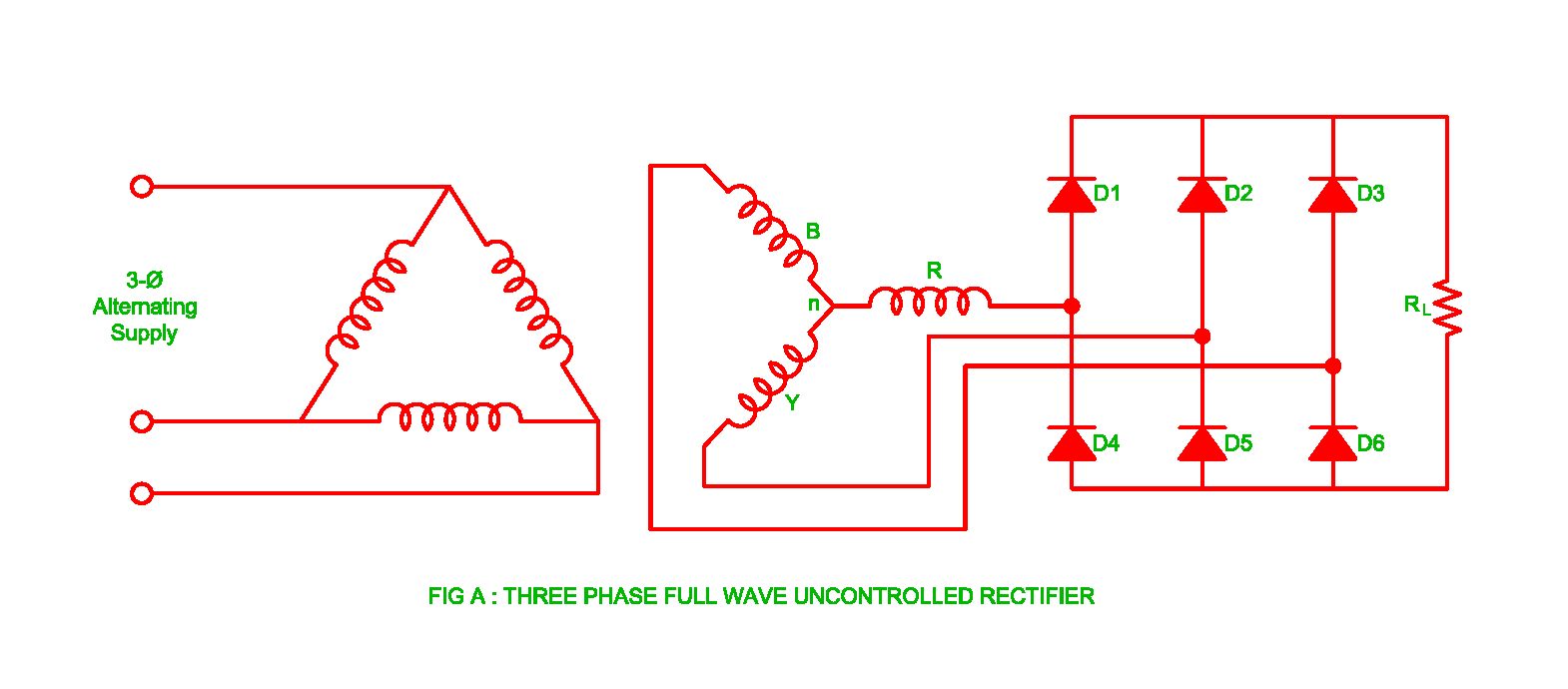
Working of Three Phase Uncontrolled Full Wave Rectifier | Electrical

Center Tapped Full Wave Rectifier - its Operation and Wave Diagram

Basic synchronous rectifier circuit. | Download Scientific Diagram